 Tweet
Tweet
My NP transfer case was causing the dreaded CD orange blink after going from 4H to 4HLC.
The error code was 33, which is the Centre Diff switch. There are 5 switches that confirm the TC shaft has moved to the correct position after being commanded by the computer.
This is a ‘driveway’ technique, avoiding expensive Mitsi dealers or hoists. If you have access to these facilities, by all means go ahead.
BACKGROUND
Interestingly, this is the SAME switch I had replaced by a misti dealer a mere 15 months ago after throwing the same code. A call to the same stealer that fixed it last year said parts only have a 12 month warranty. WTF…the first switched lasted 13 years!!! I mean..geees...I seriously have a case to take it further under Australian Consumer Law if I wanted to.
However, since I’m selling the car and the buyer wanted it fixed before they’d take it…it was urgent; so I did it myself.
I had received a 2nd hand switch from a donor transfer case (thanks nj_swb).
TIME TAKEN
By myself it took me about 3 hours from start to finishing cleanup. The dealer charged me $240 labour last time it was replaced, plus I’d bought the new genuine switch earlier and provided it to them..can’t exactly remember the price I paid - about $100). On eBay you can buy a switch for less than $50.
DIAGNOSIS
Firstly, I assume you have a orange CD light flashing meaning there is an error in the transfer case; you need to diagnose the cause. It could be a input or output shaft speed sensor, or a switch that determines the position of the shaft internal to the transfer case when changing between 4WD modes.
There are many threads on this in the forum to help. I’m not going into the details of diagnosis.
I have a MUT which allowed me to directly interrogate the Super Select 2 (SSII) to determine the error code and to watch the switch positions change ‘live’.
This determined code 33 - Centre Diff switch.
However, there is a way to force the orange CD light to ‘blink’ and report the error code without the MUT3. Can anyone help by explaining how?
Depending on the code, you can determine which transfer case switch is causing the problem.
See this thread to work out how to diagnose it, and order a replacement switch.
LETS GET STARTED - PARTS AND TOOLS
To do it, the tools you need are:
a. jack (to support he transmission as you ‘drop’ it to get access to the switches).
b. 12mm and 14mm sockets/spanners to undo the propellor shaft from the rear diff
c. 14mm socket to undo the transmission support bracket bolts
d. multi meter to confirm the switch is actually faulty
e. something to support the propellor shaft once free and undone.
f. a new replacement switch (durr)
g. Patience. And lots of it. Don’t do this job without it… trust me. A lot of it was done by ‘feel’
Here’s the process I followed.
SAFETY FIRST
1. Put transmission in 2WD, Neutral, handbrake on, and the wheels chocked. Use 2WD/ N because you need to rotate the propellor shaft to align during re-assembly.
Wear safety glasses stop dirt falling in your eyes.
UNDO PROPELLOR SHAFT AT THE REAR DIFF.
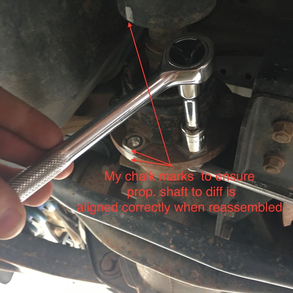
2. Mark the alignment of the prop shaft to the diff, as you need make sure they’re lined again up when reassembling. I used a chalk pen.
3. remove the bolts holding the prop shaft to the rear diff (12mm spanner and 14mm socket head). You can get to all but the very top bolt. So I un-chocked the wheels and ’rolled’ the car forward about 15cm to cause the prop shaft to rotate so I could then access the remaining bolt.
4. Once bolts are removed you need to ‘detach’ the prop shaft from the axle. To detach it I had difficultly. Taps of a hammer were unsuccessful.
CAUTION: Do not tap the shaft itself as it is carbon fibre and brittle. I was tapping the steel end part of the prop shaft. After no success I decided on a risky method. (I was alone). I put several old ‘pillows’ under the shaft to catch it as it would fall. I started the car and quickly put it in R to use engine torque to ‘free’ it, and then put it back to P. This worked…with a tiny bit of gear grinding as it fell - quickly turned off the engine. Not pretty, but worked. (I’m hoping a mechanic than I can explain a better procedure for this step)
The prop shaft fell just 15cm onto a soft landing.
DROP THE TRANSMISSION DOWN
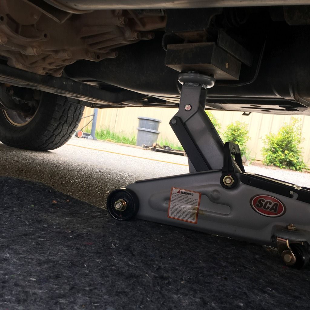
6. Make sure the transmission is properly supported by a hydraulic jack.
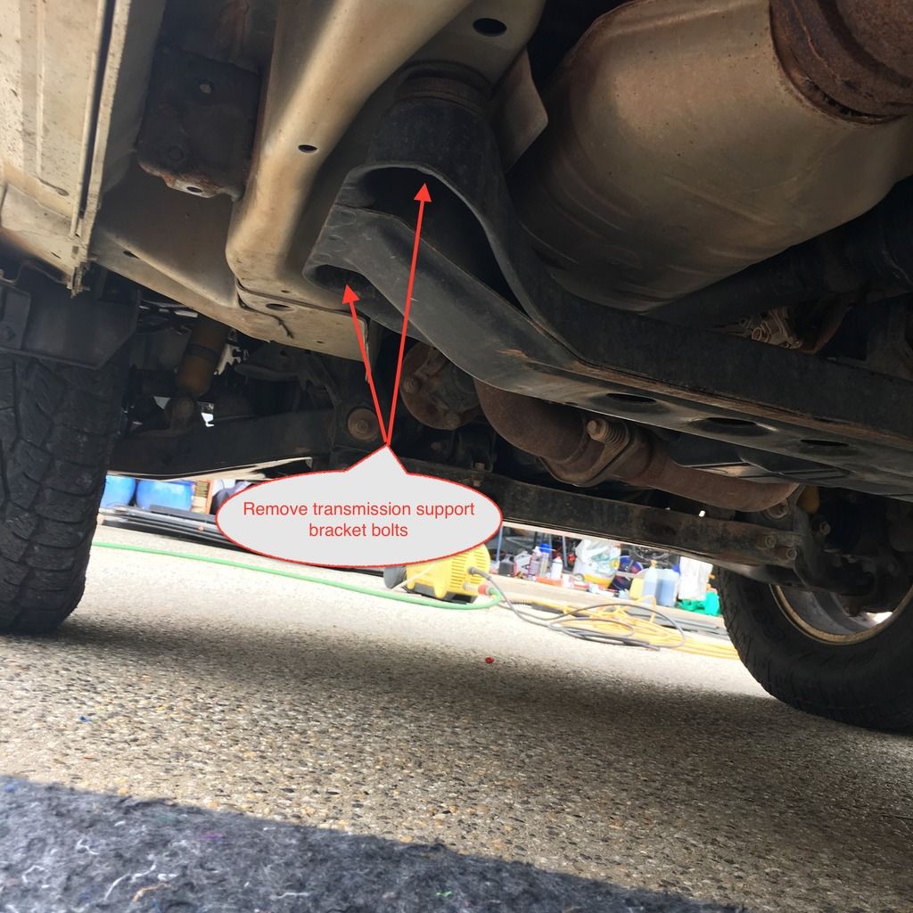
7. remove the bolts for the bracket that supports the whole transmission. (4x 14mm bolts)
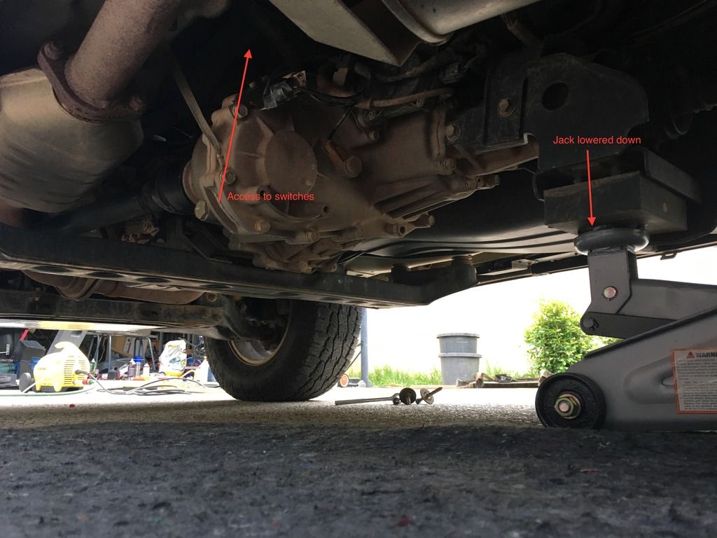
8. gentle release the hydraulic jack to SLOWLY lower the whole engine & transmission. How far you lower it is up to you. I slowly lowered it as far as I dared.
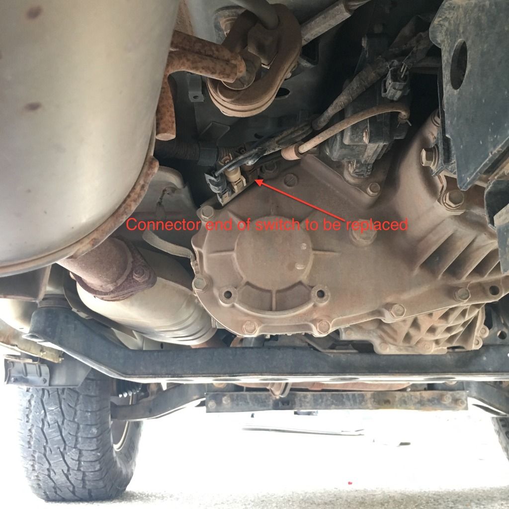
You now have physical access to the top of the transfer case where the switches are.
REPLACE THE FAULTY SWITCH
9. Disconnect the faulty switch’s plug. Mine was No 2 (brown connector) and then remove the switch plug from the metal holding bracket. Push a sharp object in the hole to pull it off the bracket
10. Now came the difficult bit. You can’t ’see’ up there. I used an iPhone with the LED light to video record the top of the transfer case and the switches. I replayed the video recording to see what I was dealing with. You can also angle the phone and see a live picture. This was really important because to locate and remove the switch is done by feel, not sight.
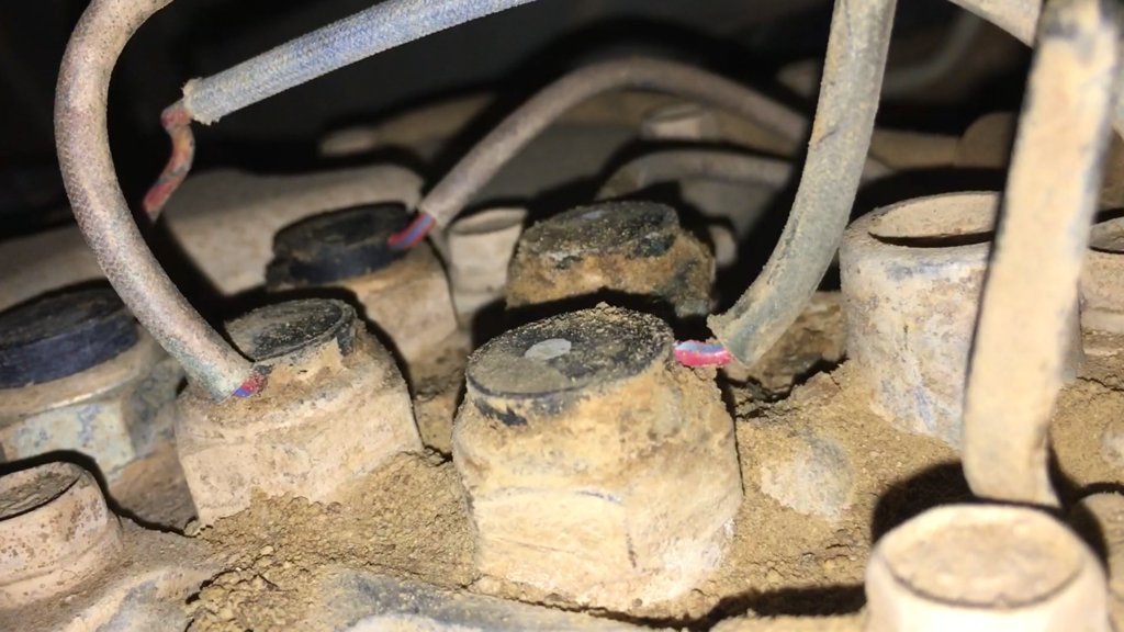
CLEAN THE AREA
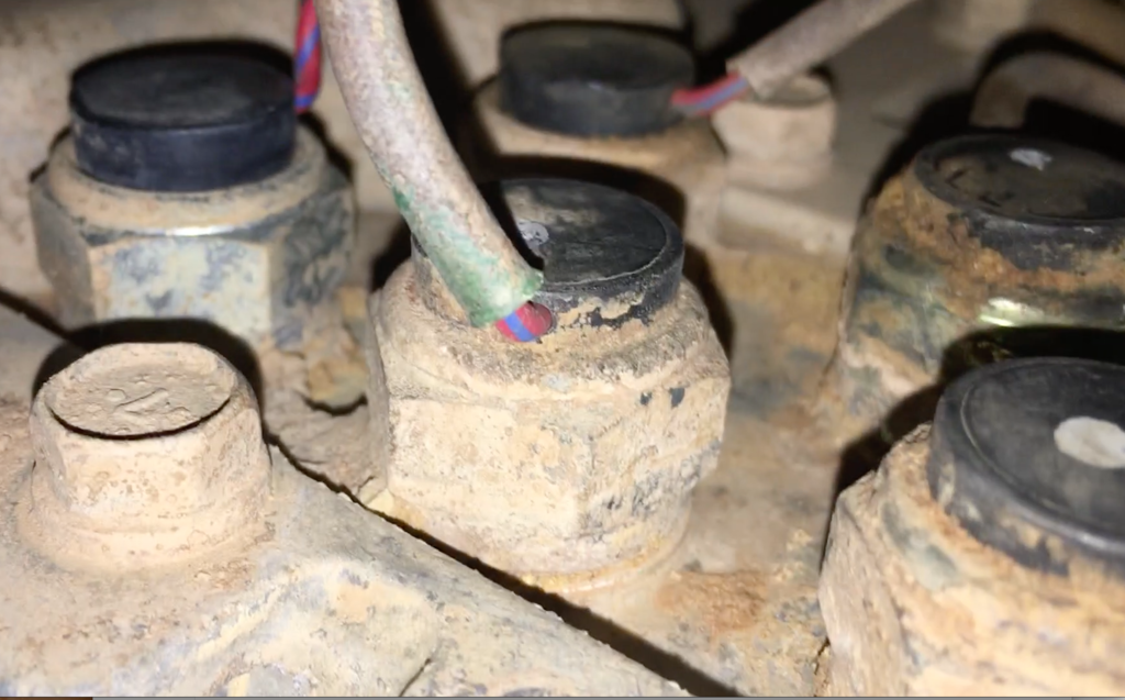
11. There was a LOT of dirt and rocks near the 5x switches. I used a toothbrush and my fingers to loosen up all the dried mud. I then used compressed air to blow away the dirt and rock. You don’t want this dirt to be around when you remove the old switch as it would be easy for dirt to enter the internals of the transfer case once the switch is removed. How you remove the dirt is up to you; water, compressed air [whatever].
BEFORE CLEANING
AFTER CLEANING
REMOVE THE SWITCH
12. Break the torque on the problem switch to be replaced. Here you need a lot of patience, a good ‘feel’ and a 22mm spanner. I used the ring end, passing the plug of the wire through the ring spanner and then pushed the spanner down the wire until it reached the switch. Unfortunately you can’t use a ratchet socket head because the wire interferes.
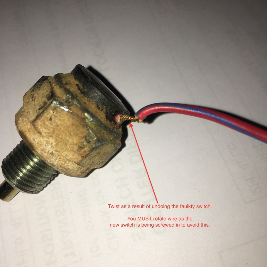
UTILISE LOTS OF PATIENCE HERE
13. Once the torque is broken, unscrew the faulty switch with fingers. I was not careful at this point as I knew the switch was buggered, but as a result the switch wire twisted and broke the insulation. This is an important lesson for when you re-install the new switch; don’t let the wire twist!
CONFIRM THE REMOVED SWITCH IS FAULTY
14. Now check the removed switch is actually faulty. Use a multi meter to check continuity between the connector’s wire and the switch housing at the other end. The housing is chassis earth. Pressing the switch in and out will cause a make or break of the connection (continuity meter beeps when closed).
This confirmed my switch was faulty, as nothing happened when pushing and releasing the switch. Practice on the ‘good’ switch to see what to expect.
If your multimeter doesn’t have a continuity feature, measure the resistance instead. The manual states <2 ohms when closed…infinity when open.
INSTALL THE REPLACEMENT SWITCH
15. Install the replacement switch; as above be careful to rotate the plug n wire as it is screwed in to ensure it doesn’t twist the wire. Use 22mm spanner to tighten up the switch. Connect the new switches plug to the supporting metal bracket which holds the other two switches’ connectors.
TEST
16. Now check the transfer case works as best as possible without starting the car, because the propellor shaft is still disconnected. Putting the ignition on (without starting) seemed to allow 2H -> 4H -> 4HLC and back again to work. Going into 4LLC didn’t. This confirmed my fault had gone away This step really depends on which of the 5 TC switches was faulty.
REASSEMBLY
17. Make sure the new switch is installed properly. i.e. clipped into the switch support bracket etc.
18. use the hydraulic jack to raise the transmission back up until until you can reassemble the transmission support bracket and bolts. Tighten all 4 bolts.
19. Reassemble the prop. shaft to the rear diff ensuring the chalk marks lineup as per prior to removal.
FINAL TEST
20. road test; and celebrate or commiserate
Hope this helps someone, someday.
The error code was 33, which is the Centre Diff switch. There are 5 switches that confirm the TC shaft has moved to the correct position after being commanded by the computer.
This is a ‘driveway’ technique, avoiding expensive Mitsi dealers or hoists. If you have access to these facilities, by all means go ahead.
BACKGROUND
Interestingly, this is the SAME switch I had replaced by a misti dealer a mere 15 months ago after throwing the same code. A call to the same stealer that fixed it last year said parts only have a 12 month warranty. WTF…the first switched lasted 13 years!!! I mean..geees...I seriously have a case to take it further under Australian Consumer Law if I wanted to.
However, since I’m selling the car and the buyer wanted it fixed before they’d take it…it was urgent; so I did it myself.
I had received a 2nd hand switch from a donor transfer case (thanks nj_swb).
TIME TAKEN
By myself it took me about 3 hours from start to finishing cleanup. The dealer charged me $240 labour last time it was replaced, plus I’d bought the new genuine switch earlier and provided it to them..can’t exactly remember the price I paid - about $100). On eBay you can buy a switch for less than $50.
DIAGNOSIS
Firstly, I assume you have a orange CD light flashing meaning there is an error in the transfer case; you need to diagnose the cause. It could be a input or output shaft speed sensor, or a switch that determines the position of the shaft internal to the transfer case when changing between 4WD modes.
There are many threads on this in the forum to help. I’m not going into the details of diagnosis.
I have a MUT which allowed me to directly interrogate the Super Select 2 (SSII) to determine the error code and to watch the switch positions change ‘live’.
This determined code 33 - Centre Diff switch.
However, there is a way to force the orange CD light to ‘blink’ and report the error code without the MUT3. Can anyone help by explaining how?
Depending on the code, you can determine which transfer case switch is causing the problem.
See this thread to work out how to diagnose it, and order a replacement switch.
LETS GET STARTED - PARTS AND TOOLS
To do it, the tools you need are:
a. jack (to support he transmission as you ‘drop’ it to get access to the switches).
b. 12mm and 14mm sockets/spanners to undo the propellor shaft from the rear diff
c. 14mm socket to undo the transmission support bracket bolts
d. multi meter to confirm the switch is actually faulty
e. something to support the propellor shaft once free and undone.
f. a new replacement switch (durr)
g. Patience. And lots of it. Don’t do this job without it… trust me. A lot of it was done by ‘feel’
Here’s the process I followed.
SAFETY FIRST
1. Put transmission in 2WD, Neutral, handbrake on, and the wheels chocked. Use 2WD/ N because you need to rotate the propellor shaft to align during re-assembly.
Wear safety glasses stop dirt falling in your eyes.
UNDO PROPELLOR SHAFT AT THE REAR DIFF.
2. Mark the alignment of the prop shaft to the diff, as you need make sure they’re lined again up when reassembling. I used a chalk pen.
3. remove the bolts holding the prop shaft to the rear diff (12mm spanner and 14mm socket head). You can get to all but the very top bolt. So I un-chocked the wheels and ’rolled’ the car forward about 15cm to cause the prop shaft to rotate so I could then access the remaining bolt.

4. Once bolts are removed you need to ‘detach’ the prop shaft from the axle. To detach it I had difficultly. Taps of a hammer were unsuccessful.
CAUTION: Do not tap the shaft itself as it is carbon fibre and brittle. I was tapping the steel end part of the prop shaft. After no success I decided on a risky method. (I was alone). I put several old ‘pillows’ under the shaft to catch it as it would fall. I started the car and quickly put it in R to use engine torque to ‘free’ it, and then put it back to P. This worked…with a tiny bit of gear grinding as it fell - quickly turned off the engine. Not pretty, but worked. (I’m hoping a mechanic than I can explain a better procedure for this step)
The prop shaft fell just 15cm onto a soft landing.
DROP THE TRANSMISSION DOWN
6. Make sure the transmission is properly supported by a hydraulic jack.

7. remove the bolts for the bracket that supports the whole transmission. (4x 14mm bolts)

8. gentle release the hydraulic jack to SLOWLY lower the whole engine & transmission. How far you lower it is up to you. I slowly lowered it as far as I dared.
You now have physical access to the top of the transfer case where the switches are.

REPLACE THE FAULTY SWITCH
9. Disconnect the faulty switch’s plug. Mine was No 2 (brown connector) and then remove the switch plug from the metal holding bracket. Push a sharp object in the hole to pull it off the bracket

10. Now came the difficult bit. You can’t ’see’ up there. I used an iPhone with the LED light to video record the top of the transfer case and the switches. I replayed the video recording to see what I was dealing with. You can also angle the phone and see a live picture. This was really important because to locate and remove the switch is done by feel, not sight.
CLEAN THE AREA
11. There was a LOT of dirt and rocks near the 5x switches. I used a toothbrush and my fingers to loosen up all the dried mud. I then used compressed air to blow away the dirt and rock. You don’t want this dirt to be around when you remove the old switch as it would be easy for dirt to enter the internals of the transfer case once the switch is removed. How you remove the dirt is up to you; water, compressed air [whatever].
BEFORE CLEANING

AFTER CLEANING

REMOVE THE SWITCH
12. Break the torque on the problem switch to be replaced. Here you need a lot of patience, a good ‘feel’ and a 22mm spanner. I used the ring end, passing the plug of the wire through the ring spanner and then pushed the spanner down the wire until it reached the switch. Unfortunately you can’t use a ratchet socket head because the wire interferes.
UTILISE LOTS OF PATIENCE HERE
13. Once the torque is broken, unscrew the faulty switch with fingers. I was not careful at this point as I knew the switch was buggered, but as a result the switch wire twisted and broke the insulation. This is an important lesson for when you re-install the new switch; don’t let the wire twist!

CONFIRM THE REMOVED SWITCH IS FAULTY
14. Now check the removed switch is actually faulty. Use a multi meter to check continuity between the connector’s wire and the switch housing at the other end. The housing is chassis earth. Pressing the switch in and out will cause a make or break of the connection (continuity meter beeps when closed).
This confirmed my switch was faulty, as nothing happened when pushing and releasing the switch. Practice on the ‘good’ switch to see what to expect.
If your multimeter doesn’t have a continuity feature, measure the resistance instead. The manual states <2 ohms when closed…infinity when open.
INSTALL THE REPLACEMENT SWITCH
15. Install the replacement switch; as above be careful to rotate the plug n wire as it is screwed in to ensure it doesn’t twist the wire. Use 22mm spanner to tighten up the switch. Connect the new switches plug to the supporting metal bracket which holds the other two switches’ connectors.
TEST
16. Now check the transfer case works as best as possible without starting the car, because the propellor shaft is still disconnected. Putting the ignition on (without starting) seemed to allow 2H -> 4H -> 4HLC and back again to work. Going into 4LLC didn’t. This confirmed my fault had gone away
This step really depends on which of the 5 TC switches was faulty. REASSEMBLY
17. Make sure the new switch is installed properly. i.e. clipped into the switch support bracket etc.
18. use the hydraulic jack to raise the transmission back up until until you can reassemble the transmission support bracket and bolts. Tighten all 4 bolts.
19. Reassemble the prop. shaft to the rear diff ensuring the chalk marks lineup as per prior to removal.
FINAL TEST
20. road test; and celebrate or commiserate
Hope this helps someone, someday.
 We loved that car.


Comment