 Tweet
Tweet
Hi guys and gals!!
At the request of some people i thought if throw up a bit of a DIY to show everyone how to make the headlights turn off when the key is taken out of the ignition position (as they should have been standard) and stop that annoying BEEEEEEEPPPPPPP we all hear when taking the keys out with the lights still on
Big props go to Ian Sharpe as i have simply copied his info i found in one of his threads (linked below) and even used the same gear

Now this is an easy mod and ive only tried it on my NW, but the mod has also been done on an NS shorty that i know of, but should work on any 4th gen Pajero.
Obviously i take absolutely no responsibility for any damages etc to other people cars because of this modification.
Things you'll need:
Phillips head screwdriver
Small flathead screwdriver
Side cutters
Stanley knife
Soldering iron and solder
Heatshrink
Electrical tape
Cable ties
Double sided tape
12v DC relay with a N/O contact
Suitable wiring
Step 1
Purchase a suitable relay and wiring
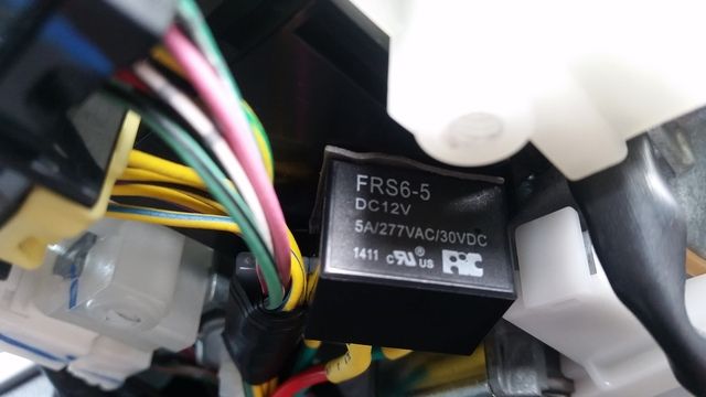
The relay i used was identical to Ians, a 12v/5A mini 2 pole relay from Jaycar (shown in pics) and i just bought 1m each of red, black and green single core wire that was slightly larger than the OEM wiring as the other stuff available was too small
Step 2
Solder the purchased wiring to the relay
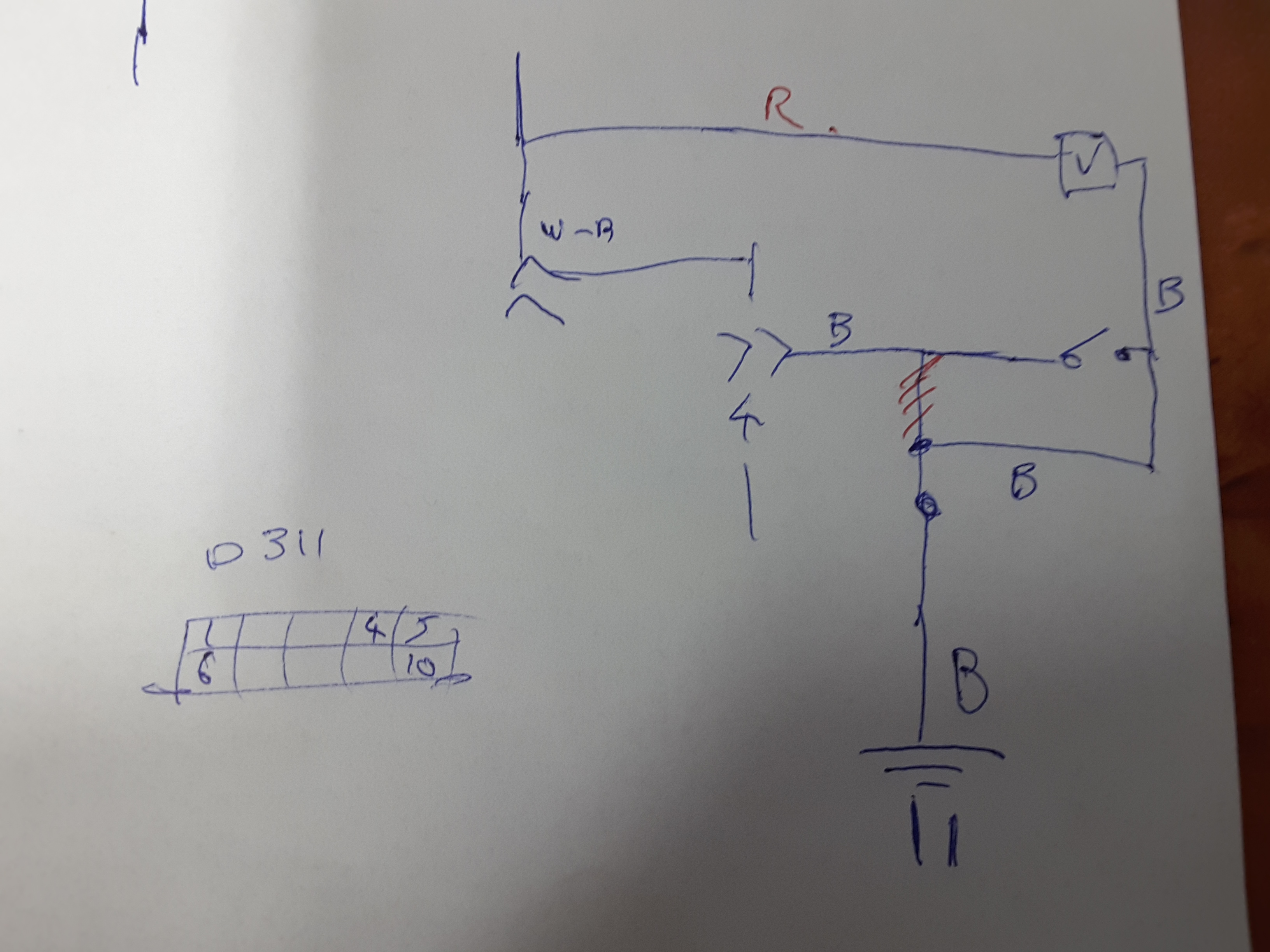
I put the red and black on either side of the relays coil, and the green for the switched wiring (for the switch wiring, one side goes to the common pin, and the other to the switched N/O contact) these relays dont have your common relay pin numbers so just look at the little diagram on the underside of the relay and itll make sense, if you are going to use a more common larger relay the pin numbering used is explained in Ians thread linked above
I only left about 1 foot of wire from each pin, but you wont even need that later on
Obviously heatshrink all soldered connections, and i also clipped the left over pins off the relay as theyre not required and dont like exposed pins lol
Step 3
Remove your steering column plastic cover
This is done by removing the two phillips head screws on the underside of the column, backing off the height adjustment lever and gently pulling the lower cover away from the top cover
If it is hard to seperate them, use a thin flat head screwdriver to gently prise the two apart at the joint, as theyre on friction fit plastic pins holding them together
Once seperated carefully remove the two halves and store them safely with the two screws
Step 4
Locate the plug and loom we will be working on
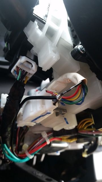
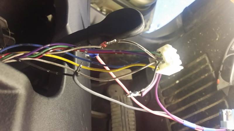
The main plug is a 10 pin plug on the left hand side plugged in vertically (shown in pics), this has the wire we will be switching (black wire) and an ignition switched wire (black and white wire) that will be the positive to the relays coil
And the loom we will steal the ground wire for the relay is directly to the right of this plug (shown in pics)
Step 5
Position and mount relay
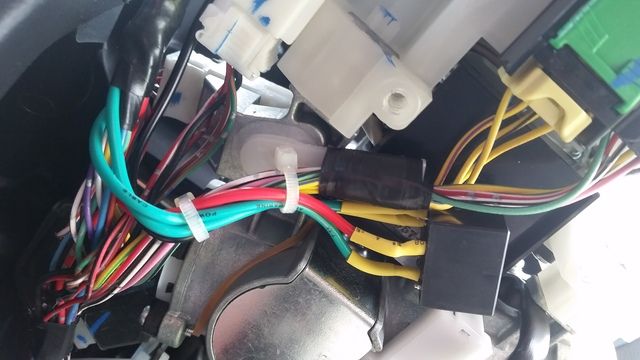
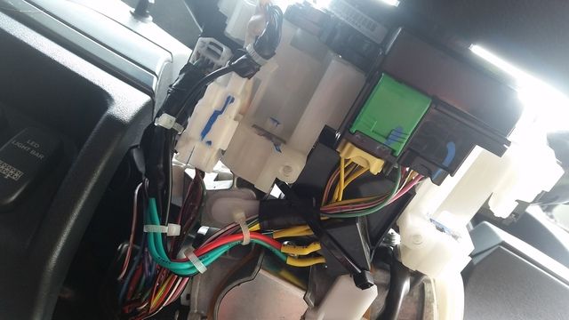
There is a nice spot the relay can be mounted with some double sided tape on the underside of the column as you can see in the pictures, i also put a cable tie carefully around the column to ensure the relay stays put
Step 5
Wire in the relay!!
Now if youre unsure about this, i recommend you disconnect the battery just to be safe
And better yet test the wiring before hand to ensure the black wire is indeed the ground and the black and white wire becomes live with the key in the ignition position
First cut the black wire to be switch and wire the two ends across the N/O contact of the relay (my green wires), solder and heatshrink the connections
** at this point you can test you have the right wire by turning the key to ignition and proving the lights wont turn on**
Next find the black and white wire in the same plug and with your stanley knife cut approx 4mm of the sheath away to expose the copper wiring, tightly join the relay coils positive wire (my red wire) to this exposed section then solder and tape the connection
With these 3 connections done i then taped the whole bit of the loom together tightly and plugged the plug back in to its socket
Now the last part is the relay coils negative wire (my black wire) and i once again used the stanley knife to remove some sheath from the black wire on the loom to the right of the plug we were working on and joined the coils negative to it and soldered and taped the connection
Thats the wiring done, try to ensure its done fairly neatly and all exposed connections are suitably taped or have heatshrink applied
Step 6
Test and tidy up!
Now is the time to reconnect the battery and test the mod
With the key out of the ignition or in the accessories position the lights should not turn on
Now with the key in the ignition position the lights should turn on
If so..youre on to a winner and you can enjoy a sip of beer for your effort
Finally tidy up the loom with a few small cable ties and ensure youre happy with the relays mounting and all your connections, then reinstall the steering column covers in the reverse of how they were removed and readjust your steering wheel to your preferred height and give it all a proper final test
Note the buzzer will sound for a second if you turn the car off with the door open, but its simply a delay on the ignition wire and nothing to worry about
CONGRATULATIONS!! Your car now does what my 1989 Subaru did from the factory lol
You can now simply leave the headlight switch in the "ON" position and not worry about draining your battery accidently
Sorry if its extremely wordy, and if anything in this DIY doesnt make sense then ask away and i will try to assist
Once again, big thanks to Ian for doing this first and showing me how it is done
At the request of some people i thought if throw up a bit of a DIY to show everyone how to make the headlights turn off when the key is taken out of the ignition position (as they should have been standard) and stop that annoying BEEEEEEEPPPPPPP we all hear when taking the keys out with the lights still on
Big props go to Ian Sharpe as i have simply copied his info i found in one of his threads (linked below) and even used the same gear
Now this is an easy mod and ive only tried it on my NW, but the mod has also been done on an NS shorty that i know of, but should work on any 4th gen Pajero.
Obviously i take absolutely no responsibility for any damages etc to other people cars because of this modification.
Things you'll need:
Phillips head screwdriver
Small flathead screwdriver
Side cutters
Stanley knife
Soldering iron and solder
Heatshrink
Electrical tape
Cable ties
Double sided tape
12v DC relay with a N/O contact
Suitable wiring
Step 1
Purchase a suitable relay and wiring

The relay i used was identical to Ians, a 12v/5A mini 2 pole relay from Jaycar (shown in pics) and i just bought 1m each of red, black and green single core wire that was slightly larger than the OEM wiring as the other stuff available was too small
Step 2
Solder the purchased wiring to the relay
I put the red and black on either side of the relays coil, and the green for the switched wiring (for the switch wiring, one side goes to the common pin, and the other to the switched N/O contact) these relays dont have your common relay pin numbers so just look at the little diagram on the underside of the relay and itll make sense, if you are going to use a more common larger relay the pin numbering used is explained in Ians thread linked above
I only left about 1 foot of wire from each pin, but you wont even need that later on
Obviously heatshrink all soldered connections, and i also clipped the left over pins off the relay as theyre not required and dont like exposed pins lol
Step 3
Remove your steering column plastic cover
This is done by removing the two phillips head screws on the underside of the column, backing off the height adjustment lever and gently pulling the lower cover away from the top cover
If it is hard to seperate them, use a thin flat head screwdriver to gently prise the two apart at the joint, as theyre on friction fit plastic pins holding them together
Once seperated carefully remove the two halves and store them safely with the two screws
Step 4
Locate the plug and loom we will be working on

The main plug is a 10 pin plug on the left hand side plugged in vertically (shown in pics), this has the wire we will be switching (black wire) and an ignition switched wire (black and white wire) that will be the positive to the relays coil
And the loom we will steal the ground wire for the relay is directly to the right of this plug (shown in pics)
Step 5
Position and mount relay

There is a nice spot the relay can be mounted with some double sided tape on the underside of the column as you can see in the pictures, i also put a cable tie carefully around the column to ensure the relay stays put
Step 5
Wire in the relay!!
Now if youre unsure about this, i recommend you disconnect the battery just to be safe
And better yet test the wiring before hand to ensure the black wire is indeed the ground and the black and white wire becomes live with the key in the ignition position
First cut the black wire to be switch and wire the two ends across the N/O contact of the relay (my green wires), solder and heatshrink the connections
** at this point you can test you have the right wire by turning the key to ignition and proving the lights wont turn on**
Next find the black and white wire in the same plug and with your stanley knife cut approx 4mm of the sheath away to expose the copper wiring, tightly join the relay coils positive wire (my red wire) to this exposed section then solder and tape the connection
With these 3 connections done i then taped the whole bit of the loom together tightly and plugged the plug back in to its socket
Now the last part is the relay coils negative wire (my black wire) and i once again used the stanley knife to remove some sheath from the black wire on the loom to the right of the plug we were working on and joined the coils negative to it and soldered and taped the connection
Thats the wiring done, try to ensure its done fairly neatly and all exposed connections are suitably taped or have heatshrink applied
Step 6
Test and tidy up!

Now is the time to reconnect the battery and test the mod
With the key out of the ignition or in the accessories position the lights should not turn on
Now with the key in the ignition position the lights should turn on
If so..youre on to a winner and you can enjoy a sip of beer for your effort
Finally tidy up the loom with a few small cable ties and ensure youre happy with the relays mounting and all your connections, then reinstall the steering column covers in the reverse of how they were removed and readjust your steering wheel to your preferred height and give it all a proper final test
Note the buzzer will sound for a second if you turn the car off with the door open, but its simply a delay on the ignition wire and nothing to worry about
CONGRATULATIONS!! Your car now does what my 1989 Subaru did from the factory lol
You can now simply leave the headlight switch in the "ON" position and not worry about draining your battery accidently
Sorry if its extremely wordy, and if anything in this DIY doesnt make sense then ask away and i will try to assist
Once again, big thanks to Ian for doing this first and showing me how it is done


Comment